Schematic drawing (not to scale) of the cross-section of the sub-detectors used in this analysis and the midpoints of the locations of the nominal and `satellite' interaction points. The long-dashed line designates a region of dense material designed to absorb all particles except muons. The short-dashed line indicates the region of the ALICE inner tracking system, which has dense material for its services on the surfaces near FMD2 and FMD3. The area between FMD2, FMD1 and VZERO-A contains only the beryllium beam pipe. The dark gray shaded areas denote the paths particles would follow from $z = 0$cm and $z = 225$cm to FMD2 and VZERO-A such that it is evident which material they would traverse. | 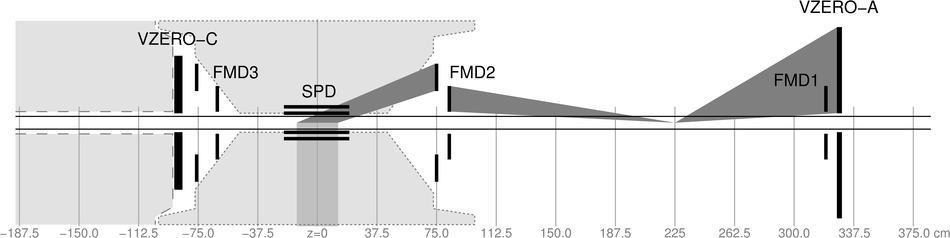 |