(left) HPTDC programming schema adopted during Run 1 and 2 (top left) and during Run 3 (bottom left) As described in detail in , in Run 3, all triggers used previously are replaced by a periodic trigger (asynchronous with respect to actual collisions) at fixed bunch crossing number ($f=33.4$ kHz), mimicking a continuous readout and covering a complete LHC orbit within three triggers All hits (short vertical blue lines) are read out and can be associated with physical events at a later stage (right) Possible selection of parameters (asynchronous trigger frequency $f_\mathrm{T}$ and matching window width $m_\mathrm{w}$) to realize a continuous readout The blue curve shows the region of allowed values The red boundaries illustrate system limitations from the HPTDC matching algorithm and HPTDC readout time constraints The green circle marks the chosen point of operation, with an asynchronous trigger rate of $\sim 33 {\rm kHz}$ and a matching window of $28.8 \mu s$. | 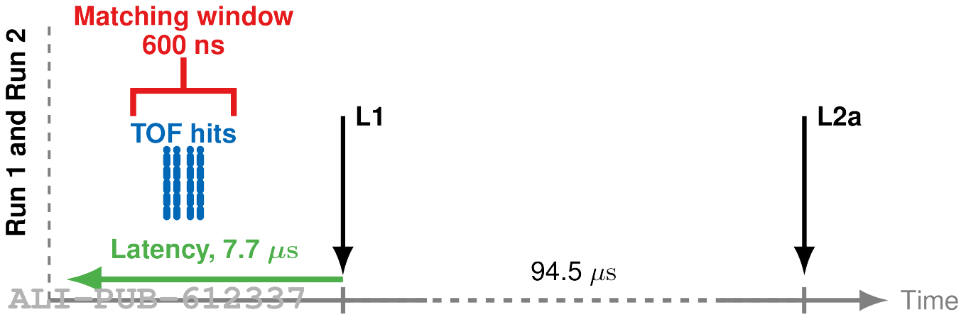  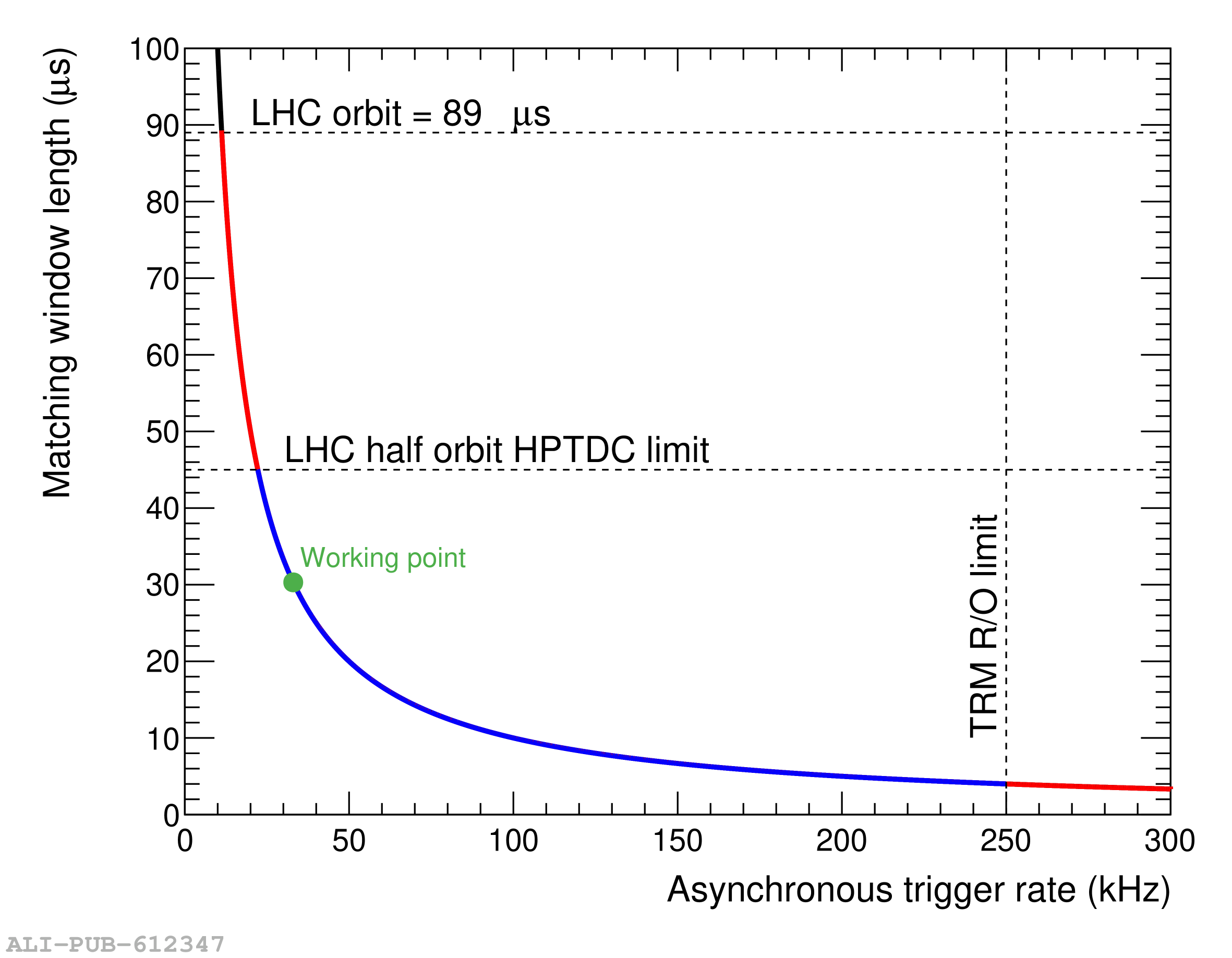 |