View of the FIT detectors illustrating the relative sizes of each component. From left to right FDD-A, FT0-A, FV0, FT0-C, and FDD-C are shown. Note that FT0-A and FV0 have a common mechanical support. FT0-A is the small quadrangular structure in the centre of the large, circular FV0 support. Note that all detectors are planar with the exception of FT0-C, which has a concave shape centered on the IP. The inset table lists the distance from the interaction point and the pseudorapidity coverage for each component. | 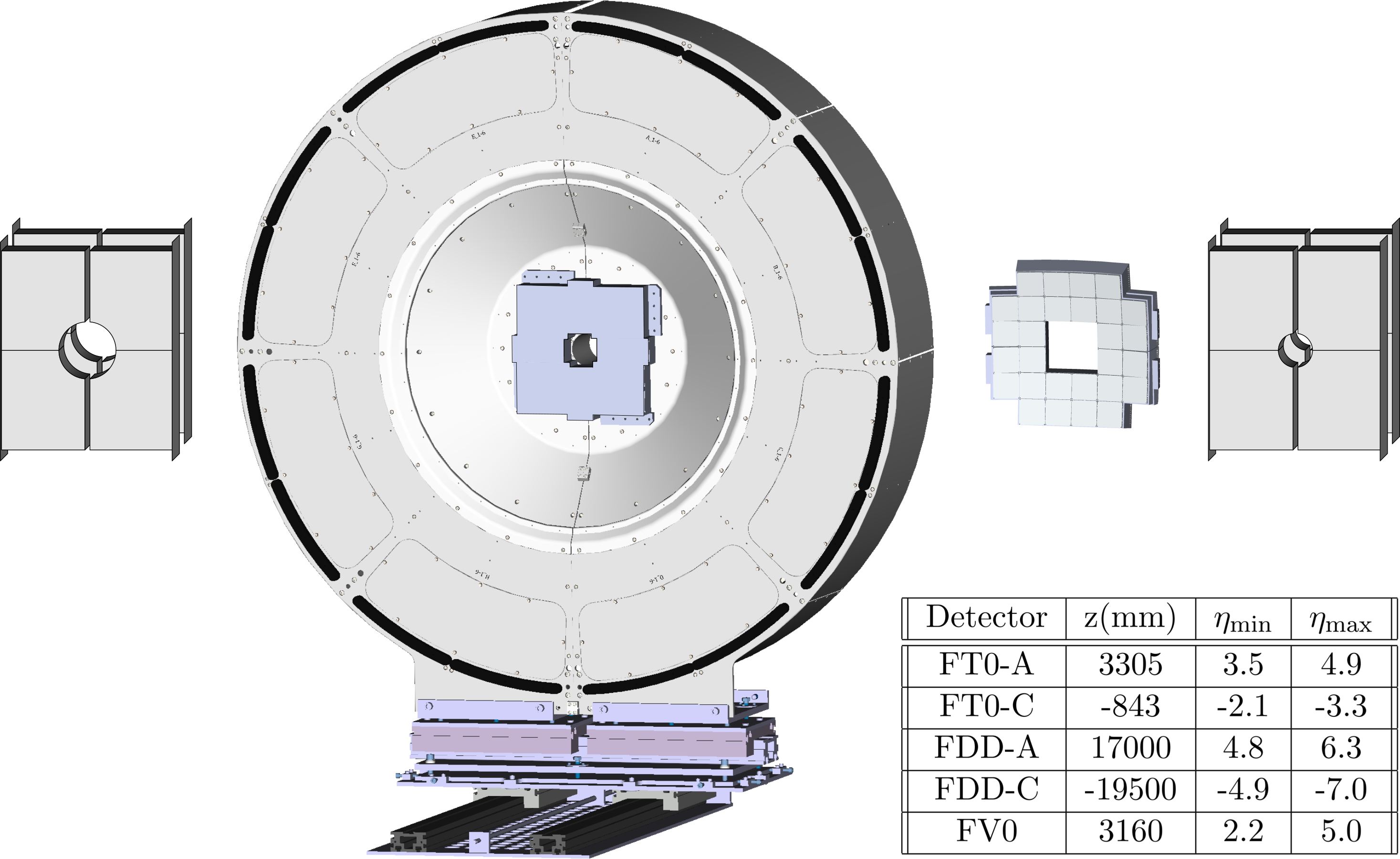 |