SDD calibration and alignment Top: distribution of track-to-point residuals in the two drift regions for the SDD modules of layer 4 side C ($z< 0$); tracks are fitted using only their associated points in SPD and SSD; the Millepede alignment corrections for SPD and SSD are included, as well as the SSD survey Bottom: residuals along the drift coordinate for one SDD module as a function of drift coordinate after Millepede alignment with only geometrical parameters and with geometrical+calibration parameters. | 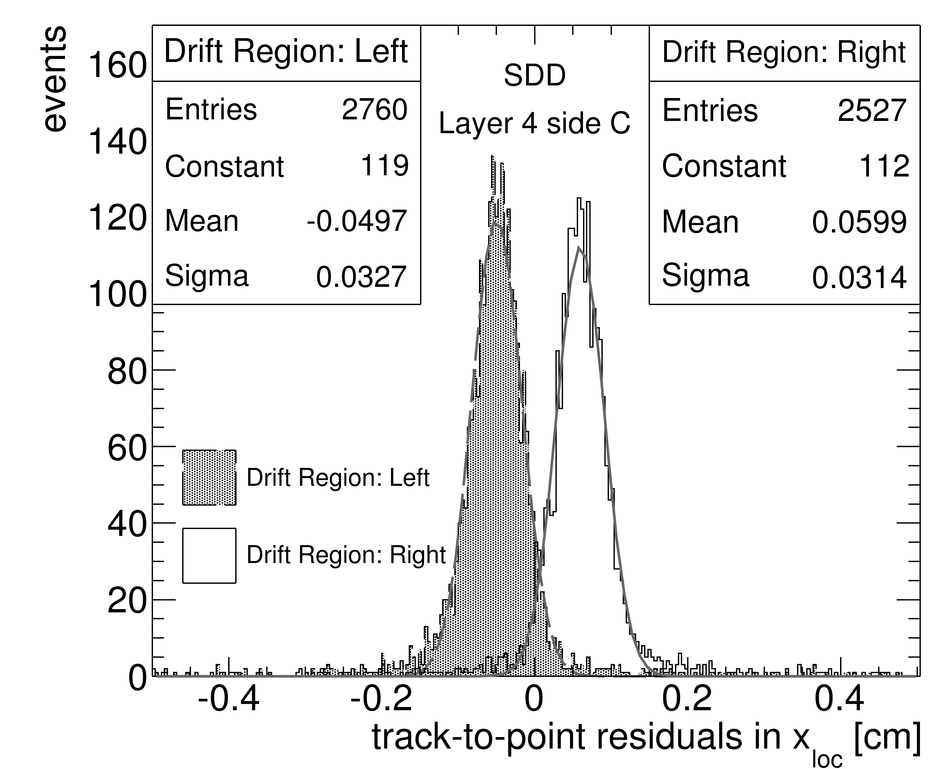  |